
This overview of inertia in renewable-heavy grids tabulates the typical inertia of rotating generators, then models the resultant Rate of Change of Frequency (ROCOF) during supply-disruptions. In our base case, a grid with 6 MW-s/MVA of inertia rides through a 2% supply-disruption, buffered by 1% fast frequency reponse (FFR), via lowering grid frequency from 60Hz to 59.5Hz and back again over a 30-second interval. From here, each MW of future reneawbles requires at least 0.1MW of FFR, most likely via lithium ion batteries and power electronics?
Power grid stability hinges on being able to maintain adequate power supplies, even when one, two or possibly several supply sources suddenly trip or go offline; or when one, two, or possibly several new loads quickly start up.
Inertia conventionally provides grid stability. When power is sourced from large, synchronized, rotating generators, the spinning masses of these generators physically store energy in their angular momentum.
If the grid suddenly needs more power, then energy can be harvested from these large rotating generators, as they will all simultaneously slow down in unison, until firing rates ramp up and restore the grid to its set point frequency (chart below, calculations in the data-file).
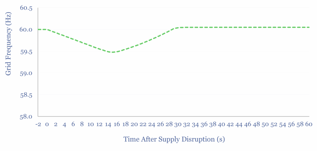
Typical goals are to keep the grid’s AC frequency within +/- 0.5 Hz of its set point, and to limit the Rate of Change of Frequency to no more than +/- 0.25 Hz/s, possibly +/- 0.5 Hz/s. Otherwise, generators may disconnect frm the grid (to protect themselves from damage), and in turn this can trigger cascading grid failures. Life is easier with more inertia and FFR.
The H-value inertia of large rotating generators is shown below, based on various studies and technical papers, tabulated in this data-file. Note the units are in MW-seconds per MVA of generation, which is mathematically equivelent to MJ per MVA of generation. 4-6 MW-s/MVA is typical.
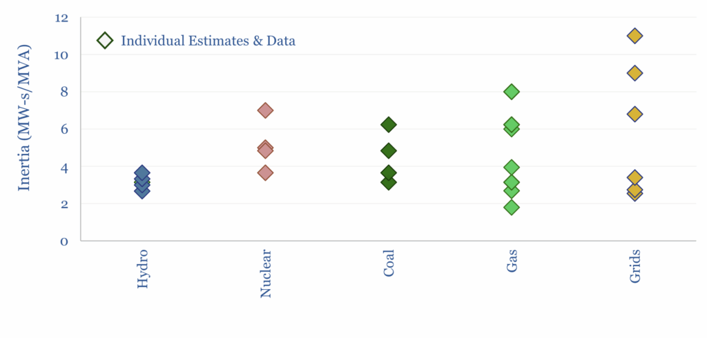
Renewable electricity sources, such as wind and solar do not inherently provide any inertia via synchronization of large rotating masses. Wind turbines do rotate, but the useful inertia of this rotating mass is perhaps closer to H = 0.5 Hz/s, per our case study here.
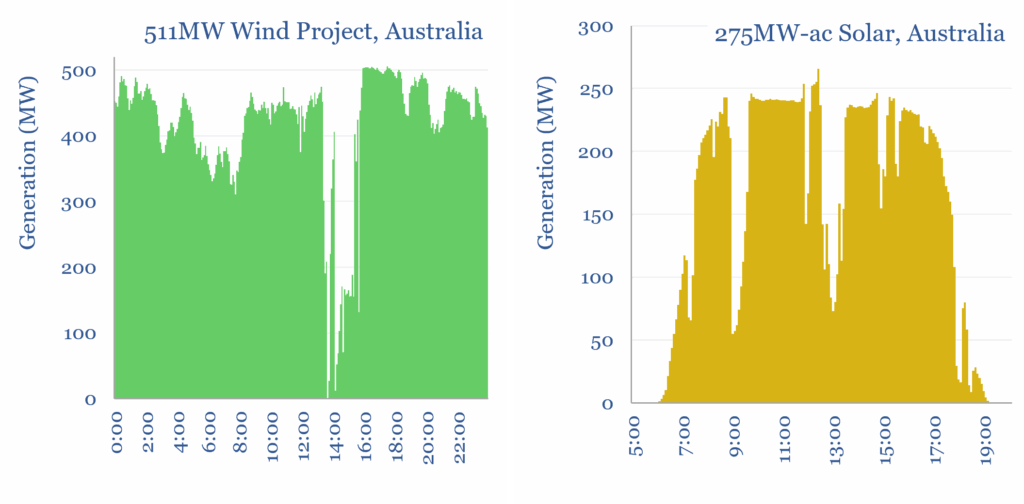
Renewable electricity sources are also prone to more volatility than rotating generators. For example, when we tabulate the minute-by-minute volatility of wind, or the minute-by-minute volatility of solar, we think these generators can drop c10% of their load within a second, e.g., when the wind drops or a cloud passes overhead (charts below).
Fast frequency reponse is needed in renewable-heavy grids to compensate for higher volatility and lower inertia. Suddenly losing 100MW is really no big deal, if you are able to ramp 100MW in replacement, within milliseconds. FFR can include grid-scale batteries, capacitor banks, flywheels, synchronous condensers, STATCOMs/SVCs and demand-side response.
Larger grids are also inherently more resilient. Losing 100MW of supply is a catastrophe in a 200MW interconnect region, but basically irrelevant in a 100GW interconnect region. So this is also a case for more transmission lines and HVDCs.
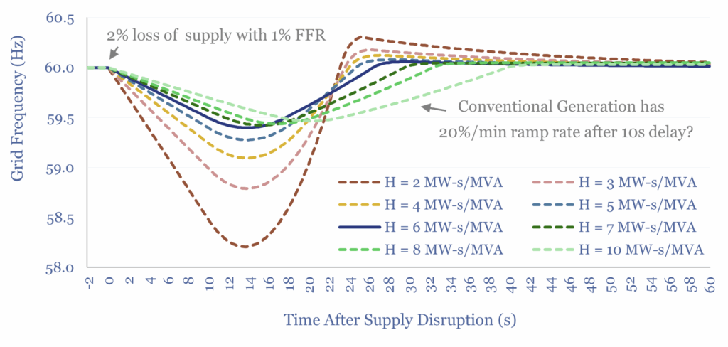
How much inertia and FFR does a renewable-heavy grid need? As an overview of inertia in renewable-heavy grids, this data-file attempts to model the answer. Although really it depends. In the scenario shown below, a grid can withstand an X% loss of load, as long as it has an [X-1%] FFR and an overall inertia of H=6 MW-s/MVA, assuming a 20%/minute ramp rate of generation sources elsewhere in the system. The calculations are in the data-file and can be stress-tested.
A grid with low inertia requires not just fast frequency response (FFR) but extra-fast, enhanced frequency response (EFR) to prevent ROCOF from spiking in the first second after a grid disruption. Ideally, via power electronics, it should be possible to response within just a few AC cycles.
A 100% renewable grid that expected to have up to 10%/second supply volatility would need to have 10% FFR, with sufficient duration to cover the shortage until some other form of generation could ramp up. In other words, supply-demand volatility is compensated entirely with FFR/EFR and not at all with inertia (because the system hardly has any!).
So as a good rule of thumb, we might assume that each MW of future renewables deployment will be co-deployed with at least 0.1MW of grid-scale batteries and/or 0.01MW of flywheels and other forms of synthetic inertia.
But depending on the inter-correlation of different renewable facilities, the grid could require 1 MW of FFR per MW of future renewables. For example, imagine a 100MW island grid, which is 100% sourced from solar, on a perfectly sunny day. Then suddenly, large, thick clouds sweep in from the West, and within 10-minutes, they cover the entire island, dropping solar output to nil. Here you would need 100MW of FFR and DSR, whose duration could ride through the ramp-up time of some kind of backup generation.
We could also deploy more batteries to bypass transmission bottlenecks and avoid curtailment by absorbing excess renewables, e.g., for battery swapping.
This overview of inertia and fast frequency response informs our outlook for global grid capex out to 2050, with an increasing reliance on batteries.